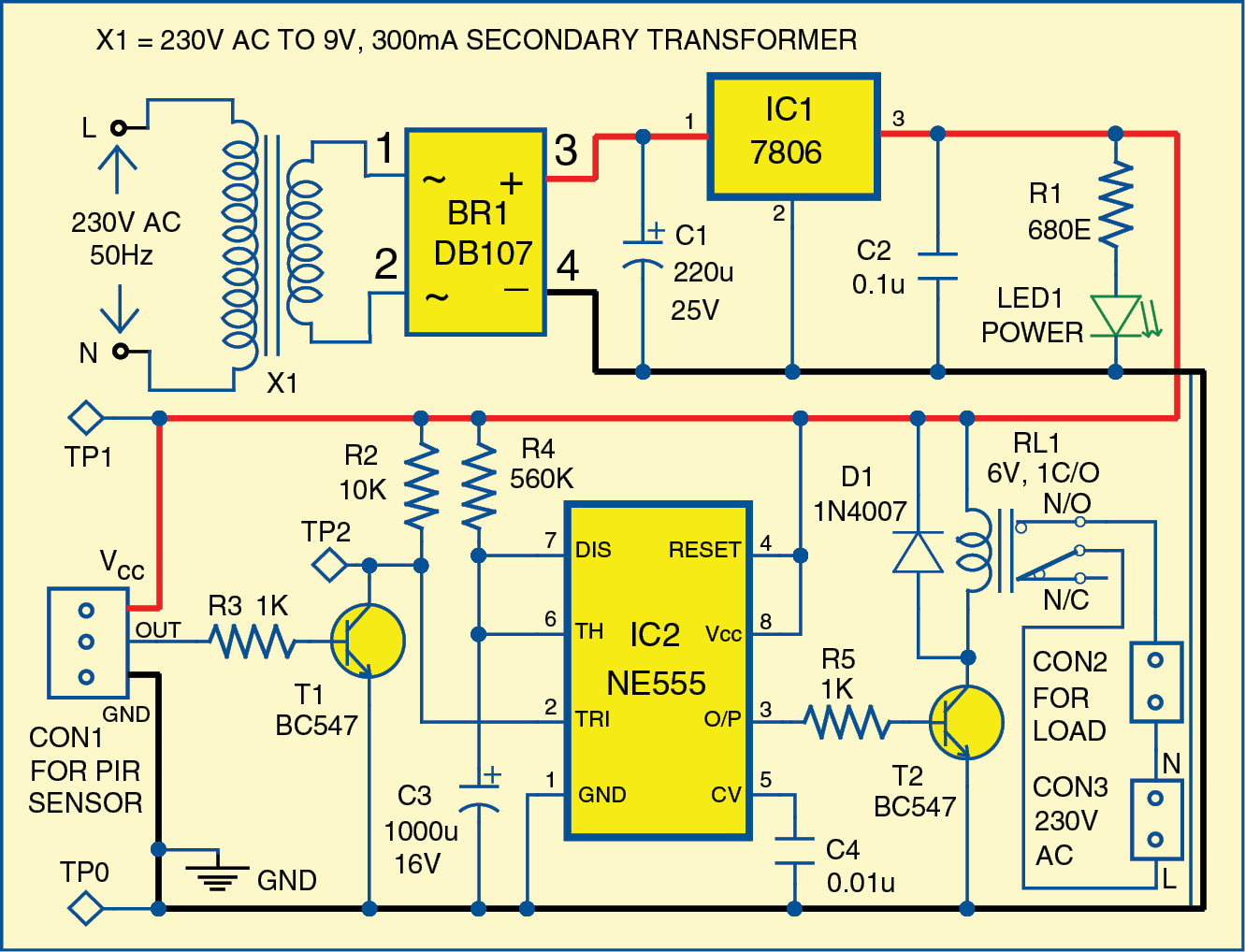
Circuit For A 555 Timer Analysis
Timer ne555 pinout datasheet block eleccircuit lm555 flop oscillator Adjustable timer circuit using 555 Circuit diagram of 555 timer ic
555 Timer Schematic : 555 Timer Delay Off Circuit Diagram | EEWeb Community
555 timer circuits 555 ic timer schematic ne555 ne555p using engineersgarage internal delay adjustable ichibot Timer 555 circuit schematic electronic circuits control ic relay using simple schematics charger board diagrams timing multivibrator battery basic choose
Analysis of 555-based pwm circuit
Internal diagram of 555 timer icTimer circuits police 555 timer latch circuit tutorial – fs pcbaDancing light using 555 timer.
555 timer oscillator diagram internal integrated555 timer ic schematic diagram : adjustable auto on off delay timer Circuit diagram symbols timerTimer 555 schematic.

555 timer circuit schematic blinking diagram delay eeweb
Simple circuit diagram using 555 timerHow does ne555 timer circuit work 555 timer tutorial: how it works and useful example circuits555 ic timer circuit diagram.
Multisim circuit motor timer 555 dc current electrical description results555 timer as oscillator 555 timer latch circuit tutorial – fs pcba555 timer circuit electronics lambert.

555 circuit pwm timer analysis based causing issues figure
555 timer circuits pdf[diagram] 555 timer chip diagram 555 timer tutorial555 timer circuits ic diagram significance shown following each figure.
How does ne555 timer circuit work555 timer diagram circuits electronic 555 timer ic pin diagram features and applicationsTimer 555 ne555 datasheet pinout eleccircuit lm555 flop.

Circuits using 555 timer
555 timer ic diagram block ne555 internal flip flop wikipedia transistor555 timer diagram chip ic block transistor tutorial discharge multivibrator does circuit logic electronics flop flip monostable bistable mode projects 555 timer analysisWhat everybody ought to know about the 555 timer.
555 sine wave generator schematic555 timer tutorial and circuits Timer rangkaian lampu disko easyeda pcb skemaHow does a 555 timer work?.

555 timer ic
555 timer ic555 timer transistor circuits driving npn mosfet bjt loads Analysis of 555-based pwm circuitIntroduction to the 555 timer.
555 timer circuit electronic circuits metronome everybody ought know components return onlineSchematic diagram 555 timer Dc motor555 timer diagram internal ic astable circuit multivibrator monostable bistable.

555 pwm circuit ltspice timer analysis based implementation figure mathscinotes
555 circuitbasics astable multivibratorIntroduction to the 555 timer 555 timer schematic : 555 timer delay off circuit diagram.
.


Introduction to the 555 Timer - Circuit Basics

555 Ic Timer Circuit Diagram

555 Timer Analysis

How Does a 555 Timer Work? - Cloud Information and Distribution

Circuit Diagram Symbols Timer

555 Timer Circuits Pdf